
The Center of Gravity of a Load: Ultimate Guide to Calculate, Locate & Balance
- What is the center of gravity of a load? Definition and core principles
- How to calculate the center of gravity of a load: step-by-step formulas and examples
- Factors that affect the center of gravity of a load and how they change stability
- Locating the center of gravity of a load: tools, measurement techniques, and practical tips
- Center of gravity of a load and safety: guidelines, common errors, and real-world examples
What is the center of gravity of a load? Definition and core principles
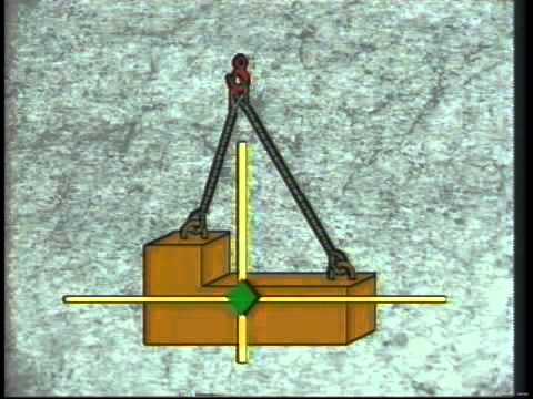
Center of gravity of a load is the single point at which the entire weight of that load can be considered to act for the purposes of static analysis. In practical terms it is the load’s balance point: if that point is supported, the load will not produce a net rotational effect about that support. Under uniform gravitational fields the center of gravity coincides with the center of mass, but the term emphasizes behavior under weight and gravity, which is critical for lifting and transport operations.
Core calculation principles treat the center of gravity as a weighted average of the positions of all mass elements. For discrete masses this is expressed as the vector sum Σ(m_i·r_i)/Σm_i, while for continuous bodies it is given by the integral of r·dm divided by total mass. The resulting coordinate identifies where resultant gravitational force and the line of action pass through the load, allowing the prediction of moments and rotational tendencies.
Several core principles govern how the center of gravity affects load behavior: the COG can lie inside or outside the material envelope of the load; its position relative to support points determines tipping and stability; and small shifts in mass distribution can produce large changes in the resulting moment. In lifting and rigging, the relationship between the COG and lifting points defines whether the load will hang level, rotate, or become unstable, so accurate assessment of COG location is essential for safe handling.
In practice, determining and controlling the center of gravity means measuring or estimating mass distribution, positioning slings or lifting gear to align the resultant load line with intended supports, and anticipating changes when loads move or liquids shift. Proper attention to COG reduces unexpected torque on cranes, slings, and vehicles and is a fundamental factor in load planning, rigging configuration, and transport stability.
How to calculate the center of gravity of a load: step-by-step formulas and examples
Step-by-step method for point loads
To find the center of gravity of a load for discrete items, use the weighted average formula: x_c = Σ(w_i * x_i) / Σw_i (and similarly for y_c and z_c). Here w_i is the weight (or mass) of item i and x_i is its distance from a chosen origin along the x-axis. Practical step-by-step:
- 1) Choose a consistent origin and coordinate axes.
- 2) Measure each item's weight and its coordinate(s) relative to the origin.
- 3) Compute the moment about the origin: multiply each weight by its coordinate.
- 4) Sum moments and divide by total weight to get the coordinate of the center of gravity.
Use the same process for y and z coordinates to get the full 3D CoG.
Example for two loads: suppose you have 100 kg at x = 0.50 m and 200 kg at x = 1.80 m. Compute moments: 100*0.50 = 50 kg·m and 200*1.80 = 360 kg·m. Sum moments = 410 kg·m and total weight = 300 kg, so x_c = 410 / 300 = 1.3667 m from the chosen origin. If you also have y or z offsets, apply the same weighted-average formula to each axis independently.
For continuous or uniformly distributed loads, replace the summation with an integral: x_c = (1/M) ∫ x dm, where M is total mass. For common shapes with uniform density the CoG equals the geometric centroid: e.g., a uniform rectangular crate 2.00 m long, 1.20 m wide and 1.00 m high has (x_c, y_c, z_c) = (1.00 m, 0.60 m, 0.50 m) measured from the corner at (0,0,0). Use standard centroid formulas for cylinders, spheres and composite bodies by dividing the shape into simple parts and applying weighted averages of their centroids.
When calculating on real lifts, remember practical rules: always choose a clear origin (edge or centerline), keep units consistent (kg and meters or N and meters), include tare or pallet weight in totals, and double-check by calculating moments about a second axis or using scales/measurements. If weights are unknown but moments are measured (e.g., by scales at support points), recover the CoG by dividing summed moments by total weight: d = Σ(moment)/W_total.
Factors that affect the center of gravity of a load and how they change stability
The position of the center of gravity of a load is determined primarily by mass distribution and geometry. Concentrating heavy components at one side or at a high point shifts the center of gravity toward that side or upward, increasing the likelihood of tipping. Long, irregular, or asymmetrical shapes move the load center away from the vehicle or support’s midline, creating an overturning moment that reduces overall stability. Even small offsets can significantly change the safe operating envelope for lifting, stacking, or transporting loads.
How the load is packed and secured also changes the center of gravity and stability. Distributed versus concentrated loading, loose items that can shift, or poorly positioned palletized goods allow the center of gravity to move during handling or transit. Attachment points, slings, and forklift forks that engage the load off-center introduce lateral moments; unsecured or high-stacked layers raise the vertical center of gravity, making the load more top-heavy and less stable under acceleration, braking, or wind gusts.
Dynamic factors — acceleration, deceleration, turns, and vibration — cause the effective center of gravity to shift relative to the support surface, amplifying instability. In motion, inertia can move the apparent load center forward, backward, or sideways, increasing the overturning moment even when the static center of gravity appears acceptable. Surface conditions and support width interact with that shifting center: a wide base tolerates larger horizontal shifts before tipping, while a narrow or uneven base magnifies risk.
Environmental and material changes can further influence the center of gravity over time. Settling of granular materials, liquid sloshing in partially filled tanks, temperature-induced expansion, or partial unloading alter internal mass distribution and therefore the center of gravity, affecting stability mid-operation and necessitating ongoing assessment and readjustment of handling methods.
Locating the center of gravity of a load: tools, measurement techniques, and practical tips
Tools for locating the center of gravity
Accurately finding a load’s center of gravity (CG) starts with the right tools: mechanical and electronic options include portable load cells or scale platforms (for multi-point weighing), a simple plumb line and protractor for suspension methods, and digital inclinometers or laser distance meters to measure vertical lines and offsets. For complex shapes, use CAD models, 3D scanning or photogrammetry to compute CG from geometry and material density. Field technicians commonly combine a few inexpensive items (tape measure, level, chalk/marker) with a calibrated set of load cells or a crane scale to validate calculations under real lift conditions.
Measurement techniques
Common, reliable techniques include the suspension/plumb-line method (suspend the object from at least two different points and draw vertical lines; their intersection gives the CG), the multi-point weighing method (place the load on multiple scales or load cells and compute the CG by taking moments about a reference axis), and the balancing/pivot method (support the load on a knife edge or pivot and measure offsets to calculate the CG). For irregular or composite loads, combine measured support reactions with simple moment equations: CGx = Σ(Fi·xi)/ΣFi, and repeat measurements with different orientations to improve accuracy. When available, software that ingests scan/CAD data can automate centroid calculations and produce coordinates usable for rigging plans.
Practical tips: always include packaging, fixtures, and any loose contents when calculating CG, and record the reference coordinate system and units. Take multiple measurements and average results; secure the load and follow safe lifting practices while suspending or shifting the object. Account for dynamic effects and sling angles—lift points that are not vertically above each other change the effective CG under load—so verify with the same rigging configuration intended for the lift. Keep calibration certificates for scales/load cells, mark the CG on the load, and document the procedure and calculations for repeatability and safety audits.
Center of gravity of a load and safety: guidelines, common errors, and real-world examples
Guidelines: Identifying the center of gravity of a load before any lift is essential to lifting safety and load stability. Conduct a pre-lift assessment that includes measuring or estimating the COG, choosing the correct sling configuration, and selecting appropriate lifting gear (spreader beams, shackles, slings) to align the rigging with the COG. Incorporate manufacturer recommendations and established industry standards into lift plans, use load charts and rated equipment, and communicate the planned pick points and taglines to the crew so the lift is executed with minimal swing and predictable balance.
Common errors: Typical mistakes that compromise safety include assuming geometric symmetry equals a centered COG, neglecting internal shifting elements (liquids, loose components, or stacked cargo), and using a single lift point on asymmetrical loads. Other frequent errors are incorrect sling angles that increase effective load on hardware, inadequate inspection of rigging gear, and failing to secure the load for transport. Each of these errors increases the risk of load rotation, unexpected tipping, or overloading lifting components, so quality control and checklist-driven procedures are critical.
Real-world examples: Practical examples highlight why COG awareness matters: a forklift handling a pallet with an off-center stacked load may experience rearward instability when lifting, while a crane attempting to lift an asymmetrical machine without a spreader bar can allow the load to rotate and damage the machine or nearby structures. Cargo on a flatbed that wasn’t positioned with its COG centered over the trailer axle may shift under braking, causing uneven weight distribution and reduced vehicle control. Mitigations in these scenarios include repositioning or redistributing cargo, using multiple rigging points or spreader bars, adding dunnage or blocking to prevent movement, and using taglines to control rotation during lifts.
Did you like this content The Center of Gravity of a Load: Ultimate Guide to Calculate, Locate & Balance See more here General Mechanics.
Leave a Reply